Fourier Transform Demonstration Applet
Introduction
Fourier Transform Demonstration (FTD) is an educational tool for visual interactive presentation of the Fourier transform (it is used in the fields like signal processing, pattern recognition, etc.).
Browser requirements
The applet has been tested with the Netscape Communicator 4.04 with JDK1.1 patch. For better experience use JIT enabled appletviewer/browser.
User manual
The FTD applet is divided into three tabbed panels (Model, Settings, About panel). The panels contain the Fourier transform wire cube, the settings for the FTD applet, and the author details respectively. The following subsections will describe each panel in detail.
Model panel
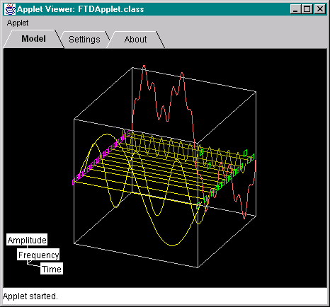
This is the main panel of the FTD applet (see picture below, sorry for the picture quality). The Fourier transform wire cube and the coordinate system are present on this panel.

The Fourier transform wire cube consists of the array of basic sine functions and the resulting signal, which is the sum of the sine functions. Dragging the mouse on the canvas rotates the wire cube and dragging a green and magenta colored square handles change the amplitude and the phase delay of a particular sine function. The shape of the cursor is changed to the cross-hair cursor when pointing at these handles.
The coordinate system is present in the lower left corner of the window. It is added for better orientation for the user. The mouse click on the time and frequency labels aligns the wire cube to the time and frequency domains respectively. The shape of the cursor is changed to the hand cursor when pointing at these labels.
Settings panel
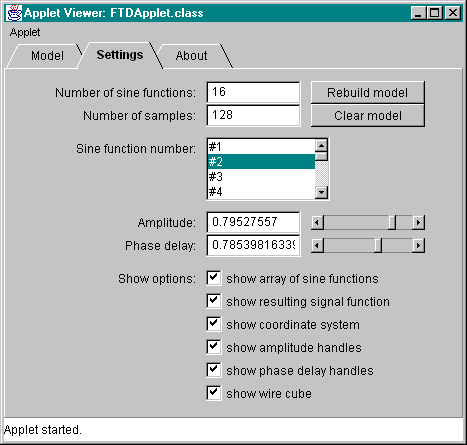
This panel (see picture below) is used for changing various parameters in the model panel. It is divided into three sections, the model settings, particular sine function settings, and the show options.

Model settings. A new model is built by filling the Number of sine functions and Number of samples fields and hitting the Rebuild model button. The Clear models button clears the model by resetting the amplitude and phase delay values to zero.
Particular sine function settings. To change the settings for the particular sine function, the function number must be chosen in the Sine function number list box by mouse double click. Then the fields and scrollbars Amplitude and Phase delay can be used to set new values. Note this can be done interactively in the model panel.
Show options. Various show options can be set in the check boxes present at the bottom of the panel.
About panel
This panel has no functionality; it displays only author details.
Typical usage
First set the new values in the Model settings of the Settings panel or use default values. Then set the amplitudes and phase delays. Rotate the wire cube to get the view of the Fourier transform, or use the coordinate system labels to align the cube to time or frequency domains. Use various show options to get better presentation. Repeat the previous tasks as needed.
When the Number of samples is low, the under-sampling problem can be experienced (see signal processing texts for further explanation). Increase the value to get rid off the problem.